DC Motors
Controlling a DC Motor
A DC 6V hobby motor is a type of direct current motor commonly used in hobbyist and DIY projects. These motors are popular among hobbyists due to their simplicity, affordability, and versatility.
Hobby motors can be controlled using various methods, including adjusting the voltage applied to the motor, using PWM (Pulse Width Modulation) signals.
Hobby motors are commonly used to drive wheels, propellers, and other moving parts in RC cars, boats, airplanes, and drones.

6V Motor with wheel
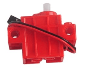
Lego DC Servo Motor
Single Motor
Controlling a Single Motor
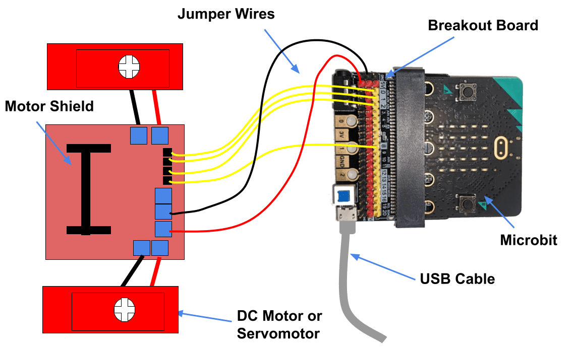
Wiring Diagram
This is the wiring diagram for both DC Motors and Servo Motors for a single motor.

Click to enlarge
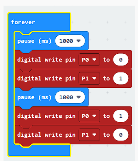
Test Code
The code below alternates which Pin is high (either pin o or pin 1). This has the effect of reversing the current, which reverses the direction of rotation of the motor.
Two Motors
Controlling two motors
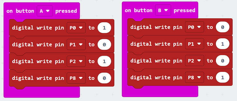
You can control two motors with a single motor control board. You simply wiring the the other motor to the opposite side and wiring the two more signal wires in from Pin 2 and Pin 8
Two Motor Test Code
DFR05 Board
Using motors with the DFR05 MotorBoard
The DFR05 is a breakout board for the Microbit the features a dedicated motor board driver which connects using the I2C protocol, meaning that most of the Microbits ports are left free for other purposes, such as for servos or sensors.
Step 1 – Connect up the hardware
Setting up and coding the DFR05 is pretty straight forward.
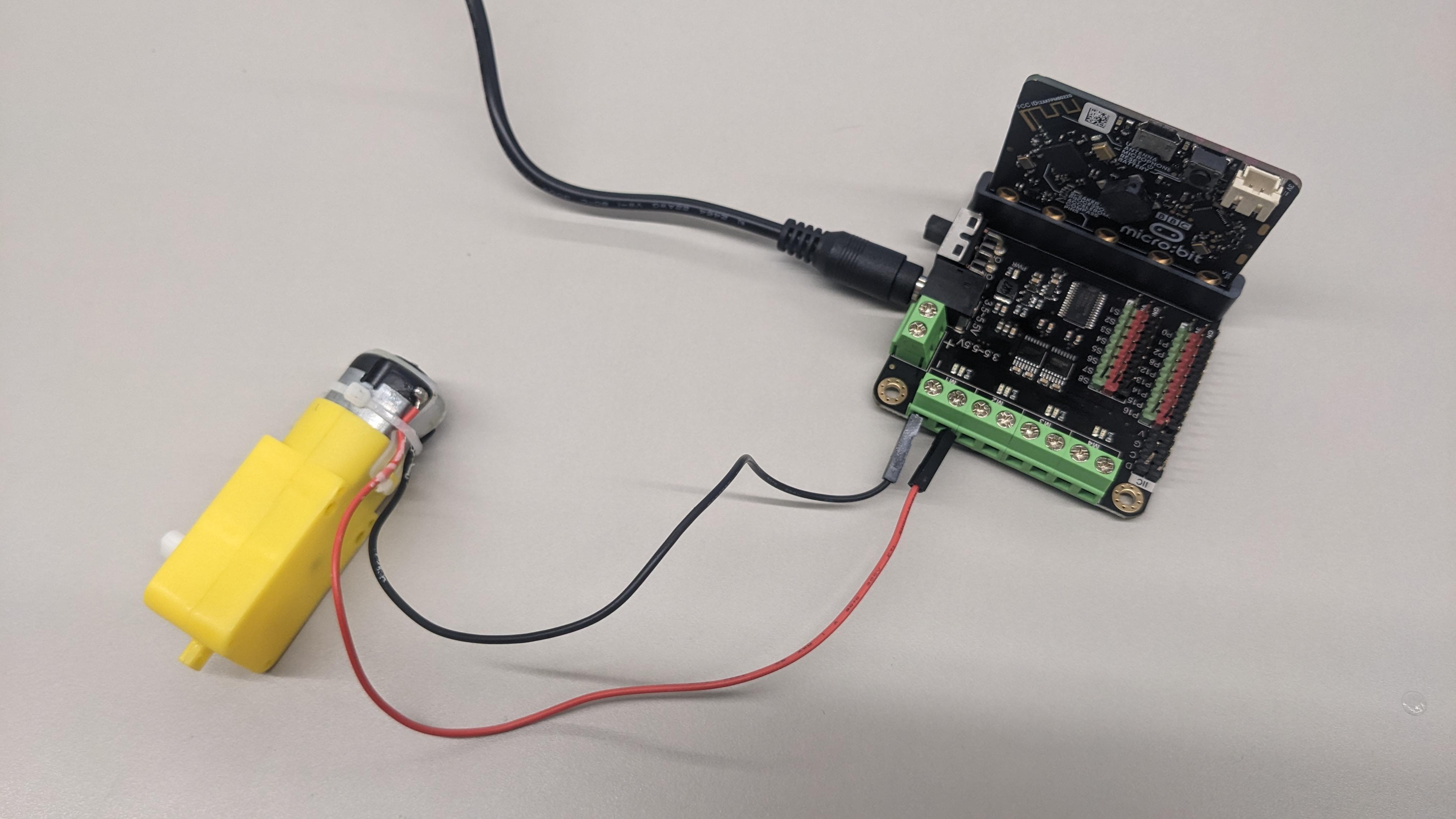
Connecting motors to your Microbit is super easy with the DFR05 Motorboard.
Points to note:
- To power the board you need to connect via the round connector on the board, not using the micro-USB connector on the Microbit itself. If it connected correctly the power LED will turn on
- The Microbit buttons need to face out/away from the board.
- There is an in-built power switch, so if the LED doesn’t turn on then check if the switch is turned on.
Coding the board
The extension isn’t one of the Microsoft Authorised extensions so you need to paste in the project URL from Github.
1, First go to extensions and paste https://github.com/DFRobot/pxt-motor into the search box
2. Then click the search icon.
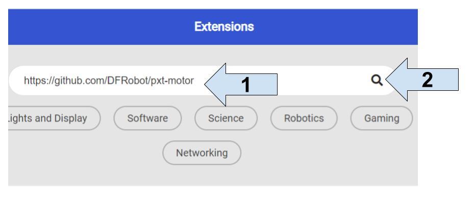
3. Finally click the project link that appears below.
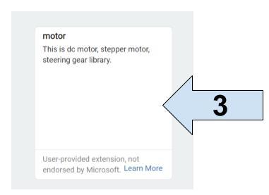
Once this is complete you can code the motorboard using the DF-driver package in the extensions menu.
![]()
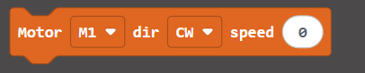
For motor control simply use the motor blocks:
Pulse Width Modulation
Pulse Width Modulation
Pulse Width Modulation (PWM) is a modulation technique used to control the analog output voltage of a digital circuit by varying the duty cycle of a rectangular waveform. PWM is widely used in electronics and electrical engineering for applications such as motor speed control, LED dimming, audio signal generation, and power regulation.
Basic Principle
PWM works by rapidly switching a digital signal between ON and OFF states at a fixed frequency. The percentage of time the signal is in the ON state (called the duty cycle) determines the average voltage or power delivered to the load.
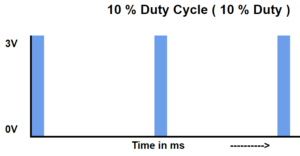
Duty Cycle
The duty cycle is the ratio of the ON time to the total period of the waveform. It is usually expressed as a percentage. For example, a duty cycle of 50% means that the signal is ON for half of the period and OFF for the other half.
Example PWM Code for a 25% duty cycle:
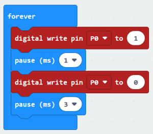
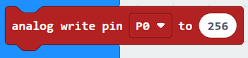
You can achieve the above automatically by using the analog write out block, which allows a duty cycle from 0 (0%) to 1023 (100%)
Frequency
PWM signals have a fixed frequency, which determines how often the signal repeats within a given time period. Common PWM frequencies range from a few hundred Hertz to several kilohertz or even megahertz, depending on the application requirements.
Simulation
Simluation
Resources