Connecting external switches and buttons to the Micro-bit

In this topic you will learn how to wire up external switches and buttons to the Microbit. This tutorial only applies to digital (off/on) buttons and switches. If you wish to to wire up an analogue switches(e.g. dimmer switch) then you should have a look at the analogue sensor topic.
Ingredients
In order to read input from external switches and push buttons, you will need the following components:
- 1 Microbit + USB lead
- 1 Microbit battery + 2 AA batteries
- 1 10,000 Ohm resistor ( or similar size)
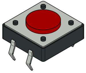
- 1 Push button or switch
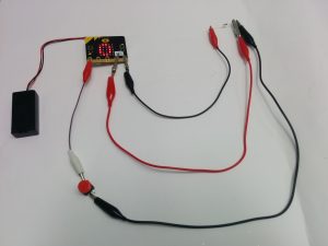
- 4 Crocodile clips
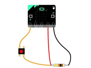
Wiring up external switches and push buttons is quite easy, you just need to use a pull-up resistor circuit, as shown in the diagrams below.
You can’t just wire the button straight through from a GPIO port (e.g. 0) through to the ground. Electrical systems are subject to electrical noise interference ( all circuits act like mini antennae) which means that the actual voltage in a circuit floats(it isn’t stable). This floating voltage can cause faulty on/off readings, which we don’t want! The pull-up / pull-down resistor solves this problem.

Click to enlarge
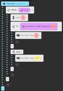
Coding the Microbit to read the digital input value is simple, you just use the microbit.readPinDigital(pin) function.

This block will return a value of:
- 1 if the switch is closed
- 0 if the switch is open
Challenge -
Challenge -
Challenge -
Challenge -
Challenge -
Challenge -

