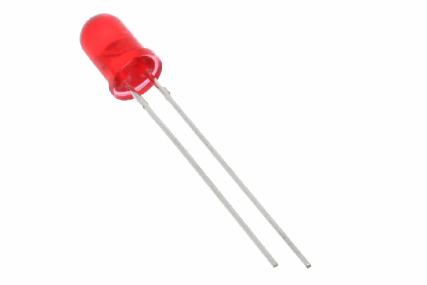
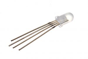
A Light Emitting Diode (LED)
is an electrical component that lights up when a current is passed through it.
- LEDs come in certain voltage ratings – you must use an LED with the correct voltage rating for it to work.
- LEDs are diodes – devices that only allow current to flow in one direction. If you plug an LED in the wrong way round it wont work.
- The short leg is usually the negative – end and the long leg is the positive end. Some LEDs also have a flat edge one their base that indicates the negative end.
- LEDs come in two varieties – Single colour LEDs that give off light of a certain colour. RGB LEDs which can be programmed to display any colour.
Wiring up an LED to the Microbit is easy, you just need:
- 2 Crocodile clips
- 1 Female to Female Jumper cable(or a third crocodile clip!)
- 1 LED
- 1 568 Ohm Resistor
- Microbit Battery pack
Troubleshooting
If the circuit doesn’t work try:
- Wiring up the diode the other way round. Diodes only allow current to pass in one direction, so it will only work one way round.
- Try using a lower value resist (about 200 ohm)
- Double check all your wires are properly connect


Example of an LED connected to the Microbit
Coding the Microbit is easy!
You simply just need to use the microbit.writePinDigital block.
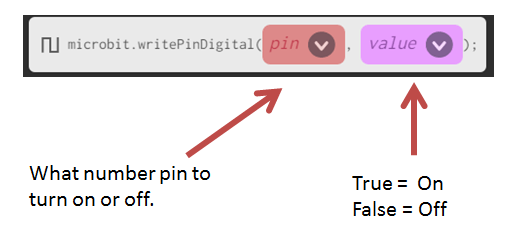
Can you guess what this code does?Have a go and find out!!!
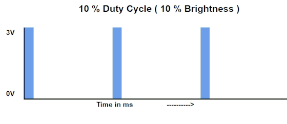
So far we have only been turning the LED on and off on the Microbit. This is great, but what do we do if we want to increase or decrease the brightness? Well we have a problem. The Microbit can only ever output at 3V. If we want to change the brightness we ideally need to be able to change the output voltage – 3V would be fully brightness, 1.5V half brightness etc. So what can we do? Well we can cheat by using a technique called pulse wave modulation.
Pulse Wave Modulation – how does it work?
With pulse width modulation the digital output port is turned on and off very rapidly, so rapidly that to the human eye it looks like the LED is dimming, but it is actually just turning on an off really quickly!
Coding the Microbit

The value can take a value anywhere between 0 and 1023. The higher the value the brighter the LED.
Here are some approximate values I tested to get the code working, definitely not scientific.
- 0 Very low power ( not off!)
- 200 Middle power
- 1023 Full power
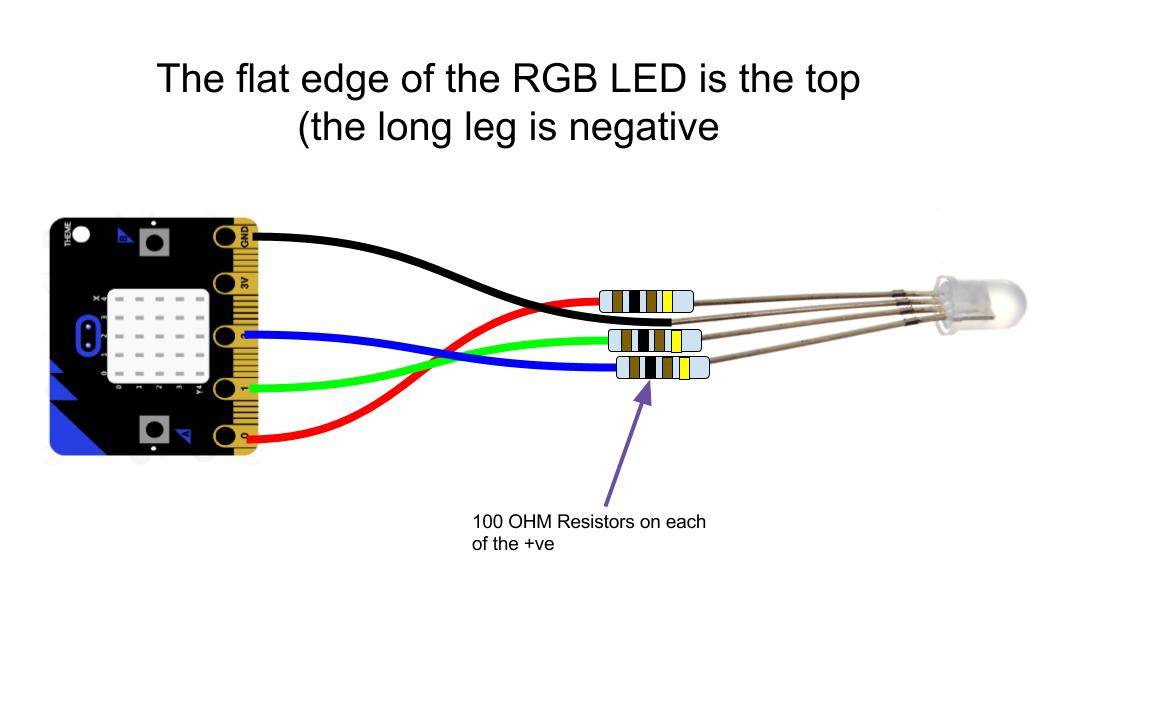
An RGB LED is essentially 3 LEDS in one:
- A Red LED
- A Green LED
- A Blue LED
Depending on the type of LED that you have, it will either have:
- A shared(common) cathode ( – ) and separate anodes ( +)
- A shared (common ) anode ( + ) and seperate cathodes ( +)
Color Addition simulator
Challenge 25 - Flashing LED
Get your Microbit to flash an LED on and off.
Challenge - LED SOS
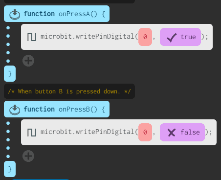
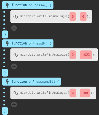
Challenge 26 - Button controlled LEDs
Every time you press a button, get your Microbit to turn on/off an LED.
Click to enlarge
Challenge - Pulsing LED
Challenge - LED Traffic Lights
Challenge - Rainbow LED