Video
Introductory Video
NOT
NOT Gates
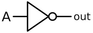
A NOT Gate is the simplest form of logic gate. It merely takes the single input and reverses the signal.
| NOT Gate Truth Table | |
| Input A | Output |
| 0 | 1 |
| 1 | 0 |
AND
AND Gates
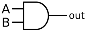
An AND Gate is gate that only produces an output if both inputs are turned on.
| AND Gate Truth Table | ||
| Input A | Input B | Output |
| 0 | 0 | 0 |
| 0 | 1 | 0 |
| 1 | 0 | 0 |
| 1 | 1 | 1 |
OR
OR Gates
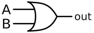
An OR gate is a type of gate that will produce an output if either(or both) the inputs are on.
| OR Gate Truth Table | ||
| Input A | Input B | Output |
| 0 | 0 | 0 |
| 0 | 1 | 1 |
| 1 | 0 | 1 |
| 1 | 1 | 1 |
NAND
NAND Gates
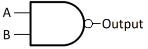
A NAND gate is a gate that only turns off both if both inputs are on, otherwise it stay on. It is made up of an AND gate feeding into a NOT gate.
| NAND Gate Truth Table | ||
| Input A | Input B | Output |
| 0 | 0 | 1 |
| 0 | 1 | 1 |
| 1 | 0 | 1 |
| 1 | 1 | 0 |
NOR
NOR Gates
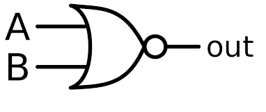
An NOR gate only turns on if both inputs are off. It is made up of an OR gate feeding into a NOT gate.
| NOR Gate Truth Table | ||
| Input A | Input B | Output |
| 0 | 0 | 1 |
| 0 | 1 | 0 |
| 1 | 0 | 0 |
| 1 | 1 | 0 |
XOR
XOR Gates
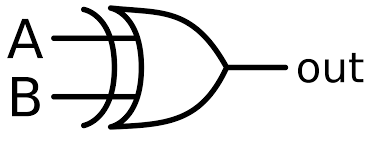
AN XOR Gate will only turn on if either (but not both) inputs are on.
| NOR Gate Truth Table | ||
| Input A | Input B | Output |
| 0 | 0 | 0 |
| 0 | 1 | 1 |
| 1 | 0 | 1 |
| 1 | 1 | 0 |
Practice
Activity 1
Have a go at connecting up multiple logic gates to see what happens, using the simulator below. Can you work out the inputs and outputs for the following examples.
https://academo.org/demos/logic-gate-simulator/
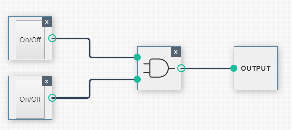
Example 1
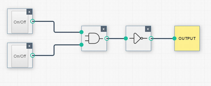
Example 2
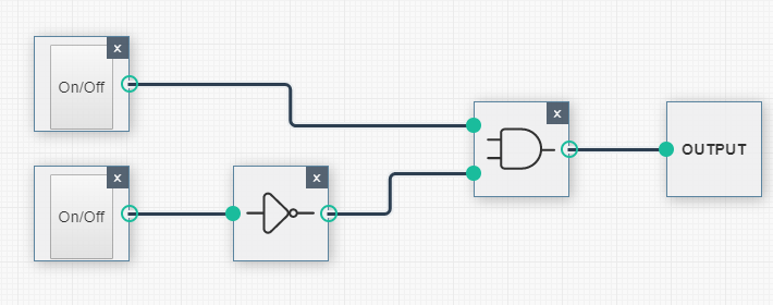
Example 3
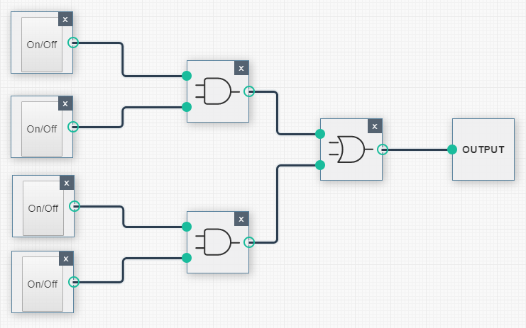
Example 4
Activity 2
Activity 2 – Applying Logic Gates
Using the link below, see if you can make the following systems:
Logic Gates Application Simulator
System 1 – Fan cooling system.
If the main system switch is turned on, then the fan will operate when:
- Every 5 seconds
- When The manual override button is pressed.
System 2 – Basic Alarm System
Make a system where if any of the 3 sensors (use 3 switches to represent sensors) are triggered, the alarm light will flash RED.
System 3 – Advanced Alarm System
Adapt the system so that:
- The alarm will not be triggered if the system has not been armed first (use another switch for this)
- The alarm should alternate between flashing red and sound a siren every 1 second.
System 4 – Button operated traffic light.
Make a traffic light that starts on green, then goes to amber – red – amber – green again.
Hint – You’ll need to flip flop!
Resources
CS Unplugged Logic Gates Activity
Past Paper Exam Questions
J15 Paper 11 Qn 7
N16 Paper 11 Qn5
N19 11 Qn3
J20 11 qn5a
J18 11 Qn4