Introduction
Types of ERD
Entity-Relationship Diagrams (ERDs) provide a visual representation of the database structure.
They facilitate communication among stakeholders, guide the database design process, and serve as documentation for the database schema.
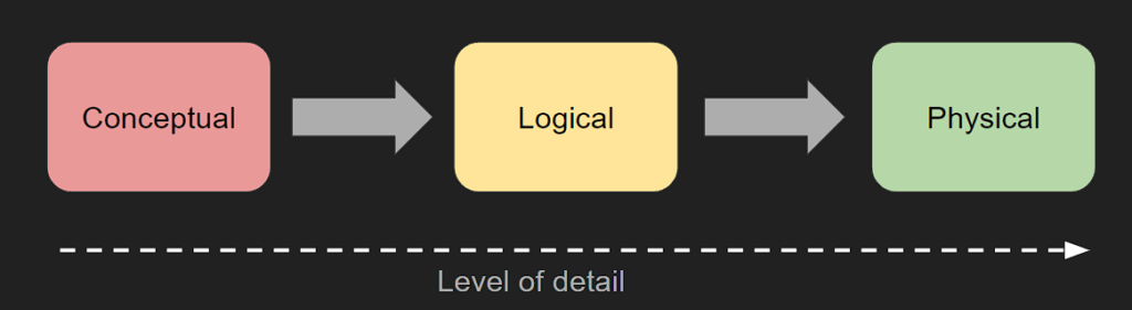
There are three types of Entity Relationship Diagrams – Conceptual, Logical & Physical.
As the project progresses and requirements became more defined the ERDs needed will move from Conceptual through to Physical.
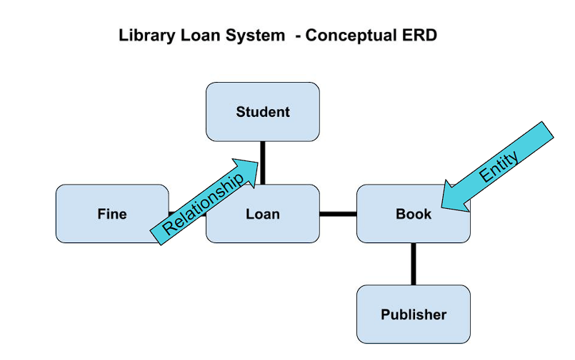
Conceptual ERD
Conceptual ERD
Click to Enlarge
- Focuses on high-level relationships between entities.
- Used in the initial stages of database design to capture essential entities and their relationships.
- Helps stakeholders understand the scope and requirements of the database system.
Used by
- Business analysts
- stakeholders
- project managers
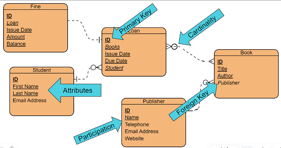
Logical ERD
Logical ERD
Click to enlarge
- Used to translate the conceptual model into a relational database schema.
- Specifies attributes for each entity, defines cardinality (one to one, one to many) and participation(optional vs required) constraints.
- Provides a detailed view of the database schema, including primary and foreign keys.
Used by
Database designers, data architects, developers
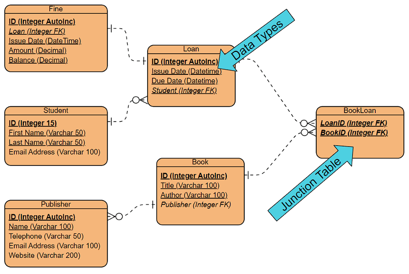
Physical ERD
Physical ERD
Click to enlarge
- Represents the actual implementation of the database on a specific DBMS in order to to build, optimize, and maintain the physical database schema.
- Includes details such as data types, indexes, storage options, and constraints tailored to the chosen DBMS.
Used by
- database administrators
- system administrators
- developers
Video
Types of ERD Diagram Videos