- Introduction
- Hardware
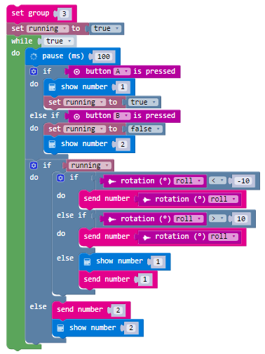
- Sender code: Digital
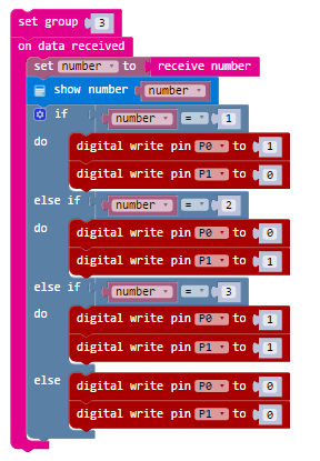
- Receiver code: Digital
- Sender unit code : Analogue
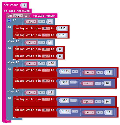
- Receiver code: Analogue
Microbit radio controlled car tutorial with L298 Motorboard
In this tutorial will we show you how to make a radio controlled car using two Micro-bits and a robot car kit (using a motorboard).
- The first Microbit will using the tilt sensor (accelerometer) to control whether to turn left or right
- The second Microbit will act as a receiver, sending the control signal to the motor-board.
Ingredients
Wiring up the Microbit radio controlled car
Setting up the hardware is easy, though it will vary depending on the motor-board that you have bought.
On the board I have used:
- The Microbit output pin 0 is connected to the motor-board input pin 2
- The Microbit ouput pin 1 is connect to the motor-board input pin 4
- The Microbit GND is connected to the Motor-board GND
Do not connect the 3V Microbit to the VCC on the motorboard!!! I did this with the first Microbit I wired up – smoke came out of the Microbit and now it is dead. RIP Microbit

The wiring setup Microbit and L298 Motorboard
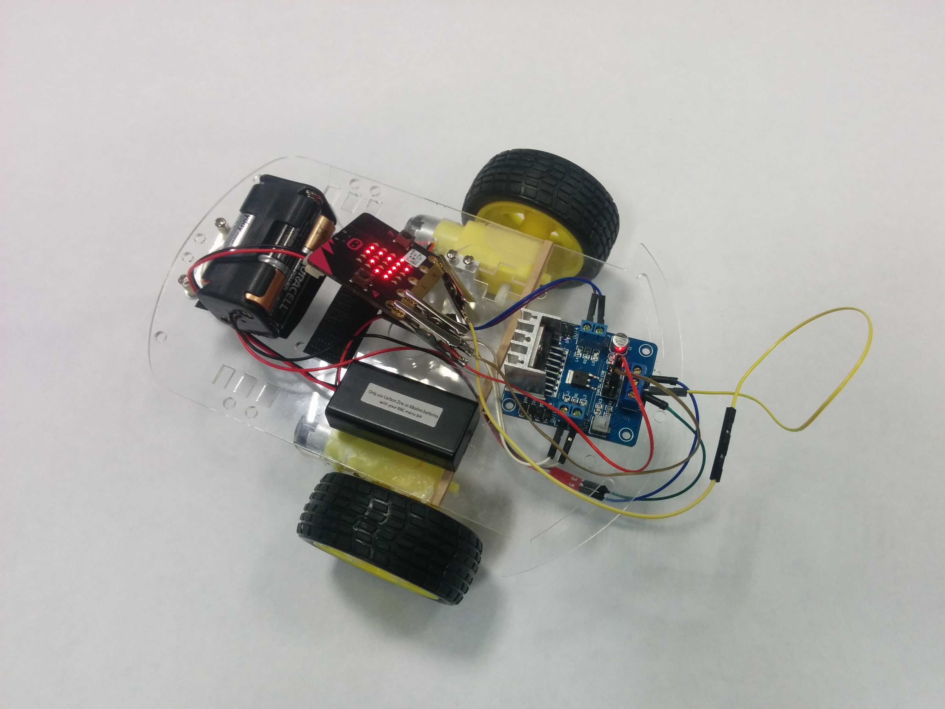
My fully assembled setup
For this tutorial we will be using the CodeTheMicrobit.com site, as JavaScript CodeKindgoms doesn’t support Bluetooth directly.
CodeTheMicrobit.com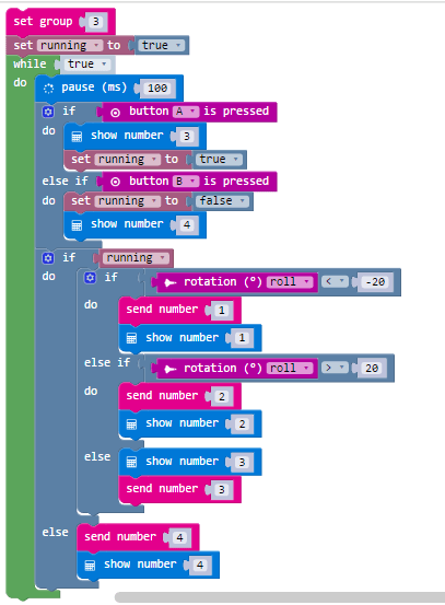
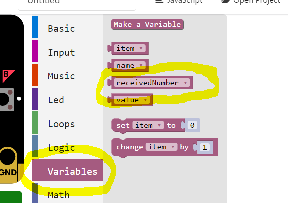
Please note that Microsoft have updated the pxt website. To find the receive number block, you need to look under the Variables menu.